Setting the DIP switches to Assign Board Numbers
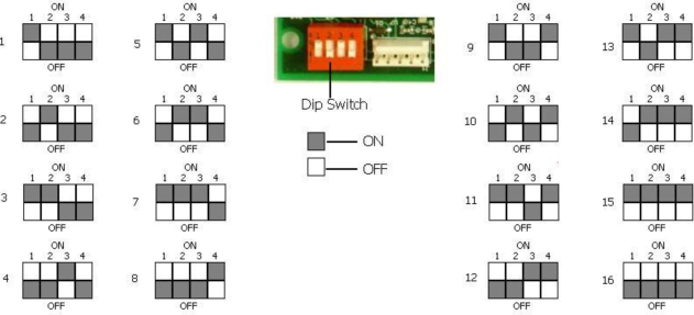
Each input board, whether directly connected in the Video Recorder or connected through a satellite box, must have a unique address assigned by the DIP switches on each input board. A unique address will ensure that the Video Recorder will correctly read all of the boards set up. If two or more boards have the same address, multiple errors could occur such as: VR reading data from one board one second, then reading data from another board the next second, no data being read from the VR, etc. It is important that each board has a unique address. Each DIP switch has four switches on it labeled: 1, 2, 3, and 4. These numbers follow a binary numbering system – i.e. 1 = 1, 2 = 2, 3 = 4, and 4 = 8. There is an ON and an OFF position for each switch. OFF = 0 and ON = 1. Each board number can be assigned by setting the appropriate switches to ON. For example, to set a board number to 1, set the “1” switch to ON and the “2”, “3”, and “4” switches to OFF ((1*1) + (2*0) + (4*0) + (8*0) = 1). To set the board number to 10, set the “1” and “3” switches to OFF and the “2” and “4” switches to ON ((1*0) + (2*1) + (4*0) + (8*1) = 10). The exception to the rule is setting a board number to 16 – all switches are off.